 |
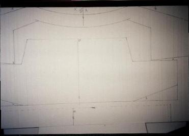
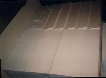
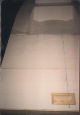
Here you can see where the hull sections are drawn on the 10 inch thick blocks of Styrofoam before cutting out. |
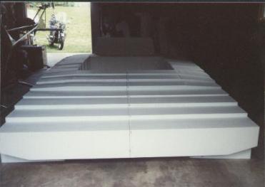
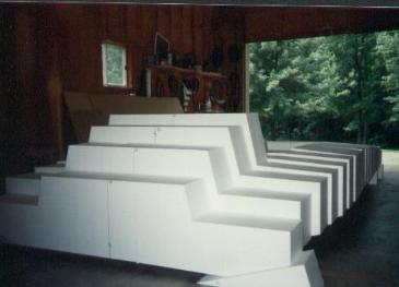
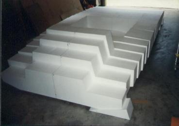
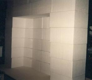
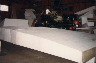
The foam blocks after being cut out are placed together for fit. There are 19 blocks total. |
 |
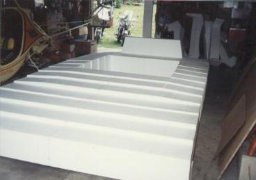 |
Another view from the rear. |
The 19 hull sections were then glued together in together in 3 sections then the 3 sections were glued together |
 |
 |
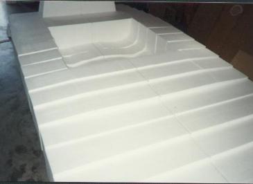
View from the front. That big lumpy thing will be the lift duct. |
Ditto. |
 |
 |
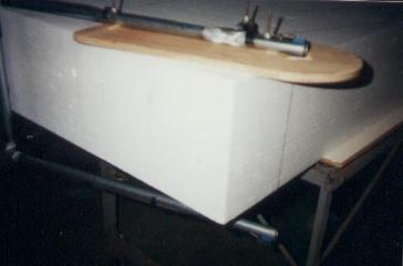
A wood section is then glued with epoxy to the rear of the craft. |
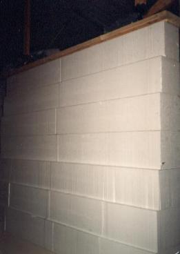
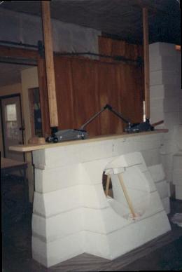
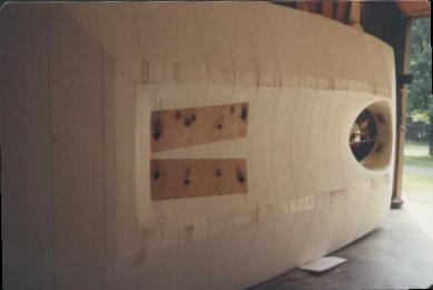
Here you can see the cockpit section of the hull. This is a view of the bottom step in the hull and you can see that there is 8 1/2 oz fiberglass between the blocks. Jacks are placed on a board with 2x4's to the ceiling putting the blocks under pressure while the epoxy sets. |
 |
 |
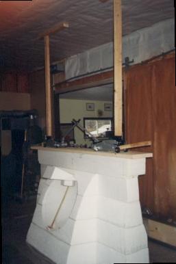
Fiberglass is set between the blocks in cockpit area only. All other hull blocks are glued. This is the cockpit site of the same section. |
 |
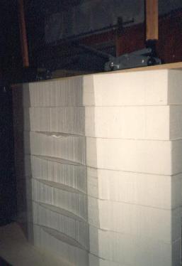
A better view of the jacks.NOTE: blocks joined with epoxy will not cut with the hot wire method. Make all cuts before gluing the blocks together! |
 |
Here the left rear of the craft is shaved with a surform, as used in autobody shops, and then sanded smooth. |
 |
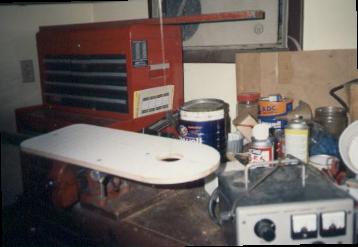 |
Here is a custom built hot wire tool. The wire is from an ice making machine with current set at 4 amps.It can be used like a hot wire band saw but it cuts small pieces only. |
Here is a close-up of the same tool in action, being used like a jigsaw. |
 |
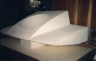 |
Here is the lift section after being cut and sanded smooth. There is a leading edge of wood set in a groove set back into the foam. |
Here is a view of the left rear after being sanded smooth. Note the seam joining the rear section to the cockpit section. Also take note of the steering box at the rear. The rudders will be controlled by a torque tube that will come from the cockpit. |
 |
 |
Another view from the rear. |
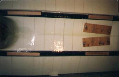
This is the bottom of the craft before glassing. The wood is for the engine mounts. Each is joined to matching wood panels on the top of the hull with 2 threaded rods each. |
 |
 |
Here is the bottom of the hull after 2 layers of glass have been added. Carbon fiber tape was added before the glass was put on, and the skids are attached to that. The shine is from extra epoxy. |