 |
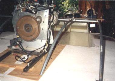
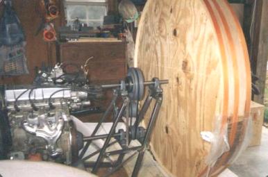
Test fitting the 1.0 liter Geo Metro engine. |
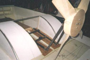
Test fit of the thrust prop. |
 |
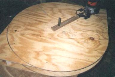 |
Using a router to cut plywood form required for the thrust duct. |
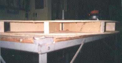
Two pieces of plywood separated by 2x4's. |
 |
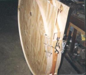 |
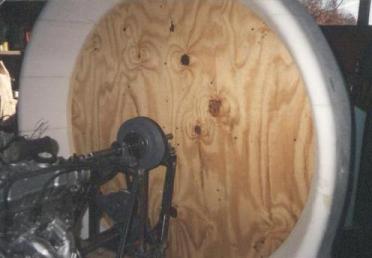
1/4th inch lauan plywood is formed around the disk. |
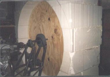
Plywood form set on drive shaft for exact positioning. |
 |
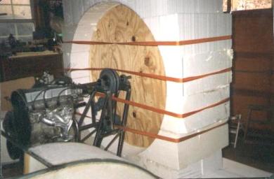 |
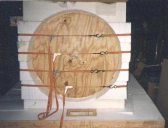
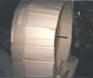
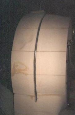
10 inch foam blocks cut and stacked and glued with epoxy. The foam is also glued to the 1/4th inch plywood that will remain when the form is removed. |
Side view of the same operation. The straps are to hold the foam to the 1/8th inch plywood while it dries. The radius of the foam was hot-wired with 1/4" radius hot-wired in the foam for the 1/4" plywood. |
 |
 |
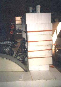
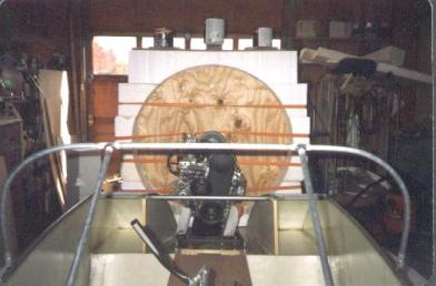
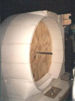
Rear view. |
View from the front. |
 |
 |
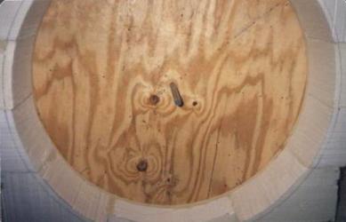
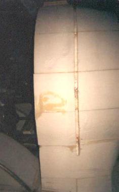
The strapping has been removed. A black has drawn where the duct will be cut. |
Another black line where the duct will be cut in the rear. |
 |
 |
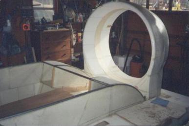
Smoothing the duct exterior with the surform. |
Turning out well I would say! |
 |
 |
All smoothed and setting up for the rudders and the trim wing using EMT. |
A channel is cut around the exterior of the duct. |
 |
 |
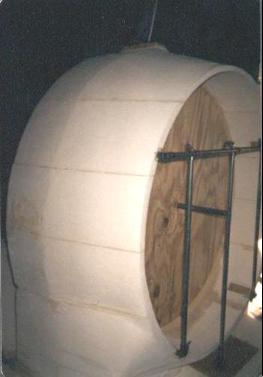
3/4 inch EMT conduit is placed in the channel adding strength and stiffness to the thrust duct. |
A view from the front. |
 |
 |
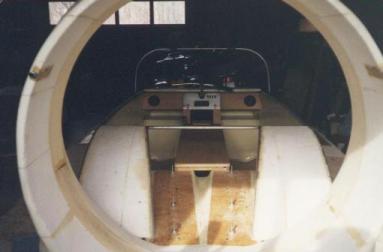
The engine and wood disk have been removed. Note the 1/4" plywood ring integrated into the duct. |
A view from the rear. |
 |